Research · spintronics
Exchange bias between magnets pointing at right angles, and the domain structure behind it
Two magnets pointing at right angles that pin each other anyway, and a pinning direction set by a field pulse rather than by cooling.
The short version
Exchange bias, one magnet pinning another across an interface, is normally described between two magnets that share an axis, and setting its direction normally means cooling the device through an ordering transition in a field. This work paired two magnets whose preferred directions are perpendicular, where that picture says neither can pin the other.
CrSBr is an antiferromagnet with in-plane spins; Fe3GeTe2 (FGT) is a ferromagnet with out-of-plane spins. They couple regardless.
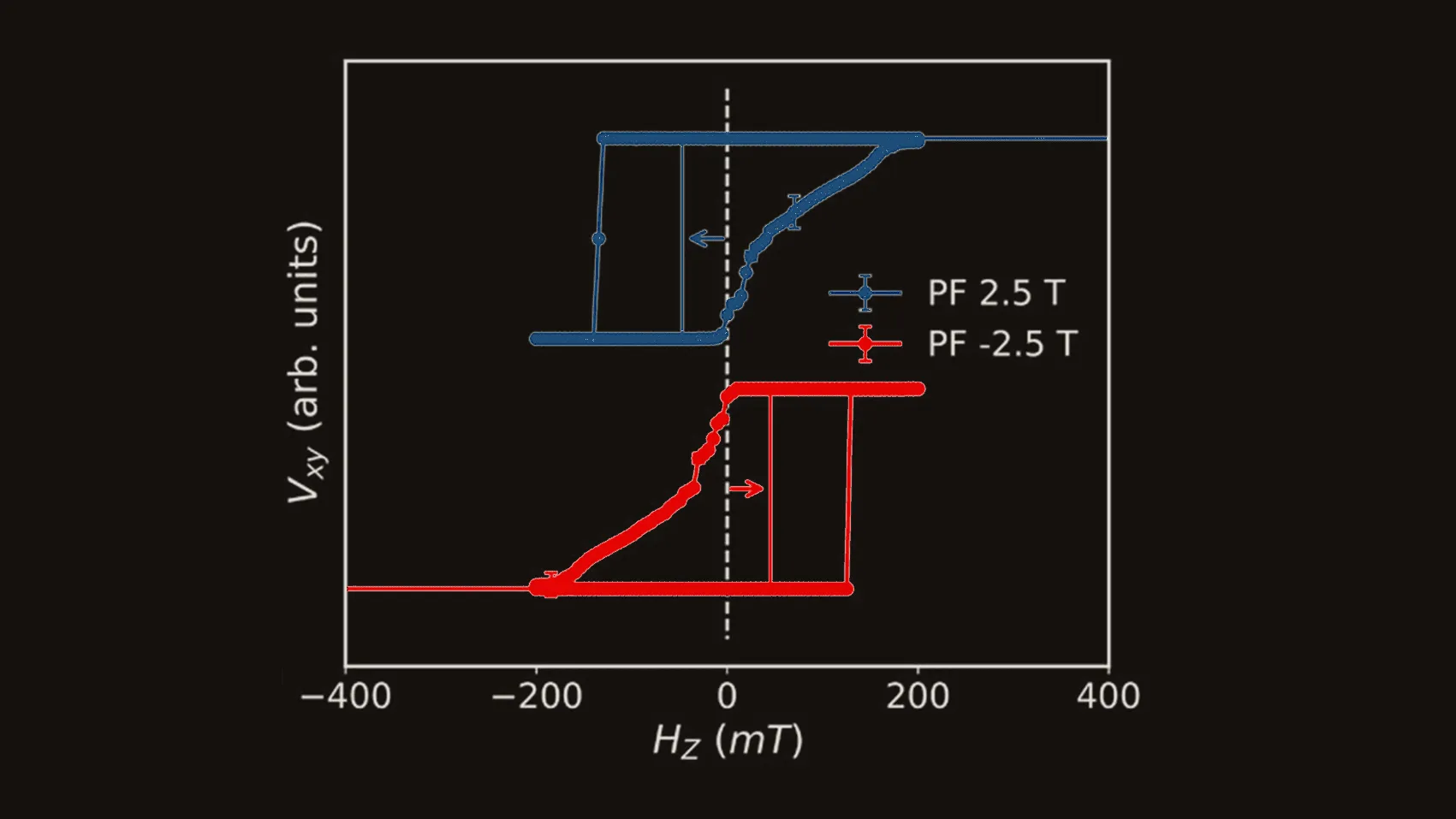
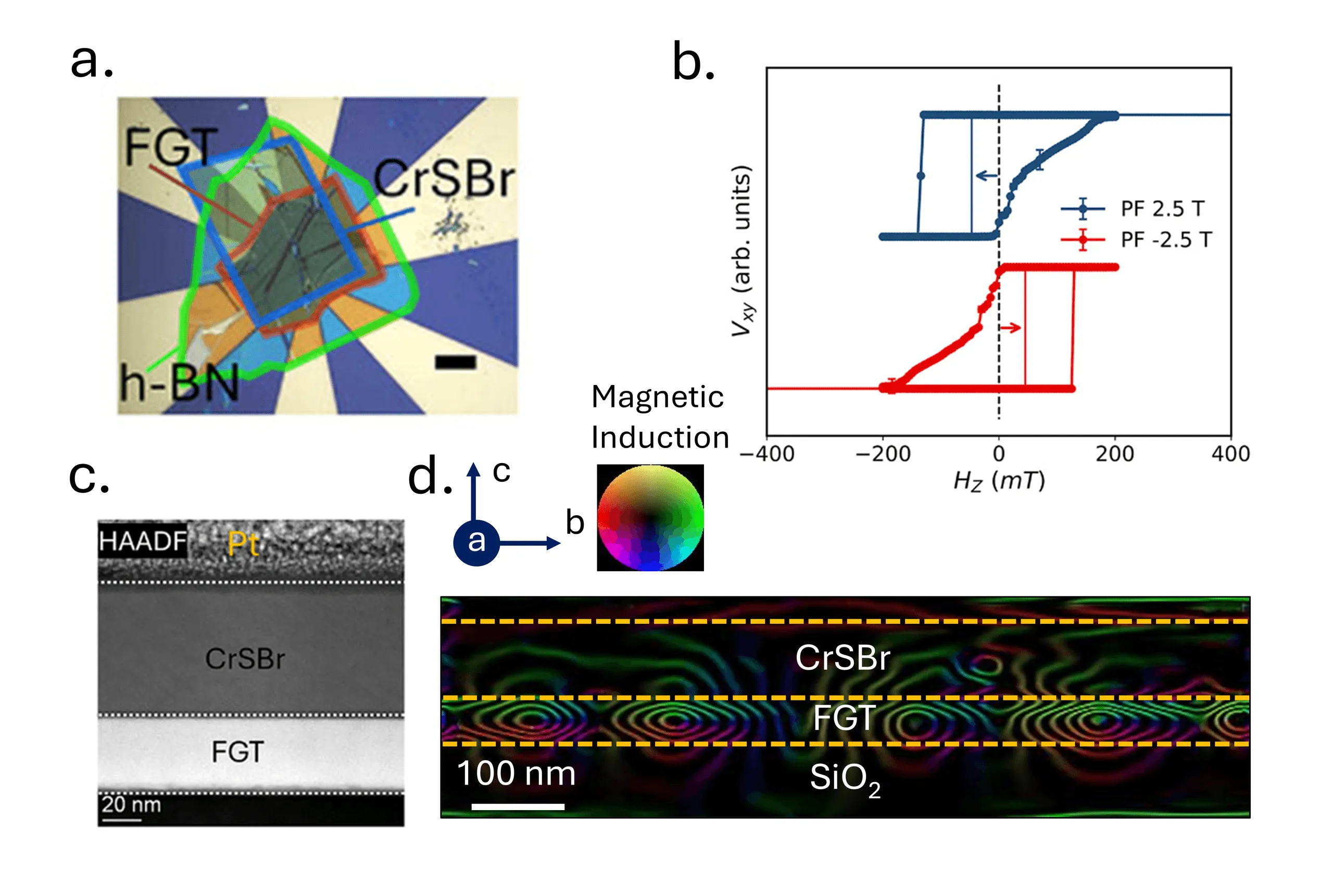 Opposite presets shift the loop in opposite directions, and the closed contours inside the FGT are the flux-closure domains that carry the coupling. Adapted from Small 21, e06284 (2025), © Wiley-VCH GmbH.
How
- Set the pinning with a ±2.5 T out-of-plane preset at the measurement temperature. Hall-voltage hysteresis loops show a bias of about ±47 mT at 10 K whose sign follows the preset, surviving up to the 132 K Néel temperature of CrSBr.
- Imaged the coupling by cross-sectional off-axis electron holography: CrSBr drives stripe-like flux-closure domains in FGT, with Bloch walls through the centre and Néel-type closure caps at the surfaces.
- Reproduced the asymmetric reversal by domain nucleation with a five-state model built from interfacial exchange, the two competing anisotropies and dipolar fields.
- Mapped where it stops working: a strong training effect, and no out-of-plane bias in the 9–12 nm FGT regime.
Sole first author. Published in Small 21, e06284 (2025), 10.1002/smll.202506284. The analysis code is public on GitHub as EB-in-FGT_CrSBr-vdW-heterostructure.